
Indian Creek Tracer Study
A sub-topic of Movement of chemicals in urban streams
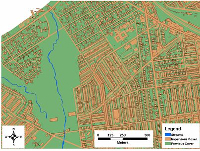
One aspect of our current research focuses on contaminant transport processes in urban streams. Like most urban watersheds, the Indian Creek watershed, located in the Overbrook section of Philadelphia, has a significant amount of impervious surface covering the land.
This results in higher storm flows and lower base flows than would be expected in a stream of similar size located in a rural or undeveloped area. However, the riparian corridor of Indian Creek is unlike most urban streams. Indian Creek has a wide riparian corridor of deciduous forest and it is protected as part of the Fairmount Park system. This wide riparian corridor likely provides some amount of 'protection' by trapping the sediment and other pollutants associated with overland urban runoff as well as providing shading and stream bank stabilization.
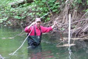
After first measuring stream flow using a velocimeter (such as the SONTEK ADV acoustic Doppler velocimeter), the appropriate mass of tracer is dissolved in a pre-determined volume of stream water.
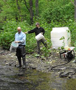
A large (1200 L) tank is used to make the tracer solution. Often, the tank is filled with stream water using a pump while tracer is added. In our latest experiment, we found it just as easy to fill the tank by hand. The solution is then slowly fed into the stream through a perforated PVC manifold placed across the stream just above the water surface. The use of the manifold allows for a more even distribution of injectate across the width of the stream. The time scale of the tracer injection tests varies from 60 minutes to 24 hours.
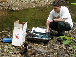
During the course of a tracer experiment, we try to estimates the beginning and end of the breakthrough curve in the field using a portable meter and a bromide ion selective electrobe (Br ISE).
Additionally, the solute concentration is measured in several wells along the stream edge and in several sampling ports within the streambed.
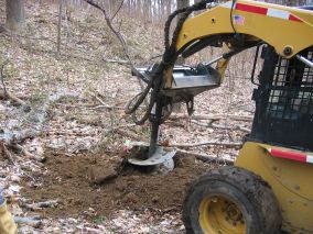
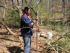
In areas inaccessible to the power equipment, we used one of two hand methods to install the wells. The first method involved using a hand auger to dig a 10 cm diameter borehole into which we placed a 5 cm diameter casing. Using this method, we were able to install wells to a maximum depth of approximatley 3 m. When groundwater was more than 3 m below the ground surface we used metal weights to hammer a small diameter (2.5 cm) hollow pipe with a steel drive point into the ground.
In addition to the groundwater wells installed along the stream bank, sampling ports are installed in the stream bed. These ports are used to collect pore water samples so that we can monitor the solute concentration in the subsurface. These ports are 1.25 cm hollow pipe. The pipe is sealed on one end and perforated over a 2.5 cm length. The pipe is pounded into the stream bed to a pre-determined depth using an engineer's hammer.
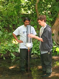
Finally, in situ streambed hydraulic conductivity is measured using a portable permeameter driven into the streambed to a predetermined depth . These measurements are made at transects evenly placed along the stream reach and also at the points where subsurface tracer solute samples are taken. The data collected during these experiments will be examined in light of stream bed topography and hydrology utilizing simple one-dimensional, as well as more complex two- and three-dimensional hydrodynamic computer models. These results will be some of the first quantifiable data collected from a real stream demonstrating the impact of the variation in streambed hydraulic conductivity on solute transport and storage.
For other CNR Areas of Interest, Check out here.